DIY Motion Simulator
- Part 1 – Project overview – What is it and what is it so much fun? 😉
- Introduction, what is this about?
- Showcase of the completed project (with video!)
- The “SFX-100” project
- Bill of materials and cost breakdown
- 3D printed parts
- Competitive landscape and price comparison
- Manuals for motors and controllers (download links)
- Part 2 – Electronics
- Part 3 – Linear actuators
- Part 4 – The rig
This is a part 3 of 4 – access all the sections of this series by using the index above.
Part 3 – Building the actuators
Now that we have the electronics ready, we’ll be building the heart of the system – actuators.
Overview of all the parts
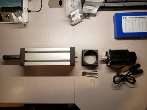
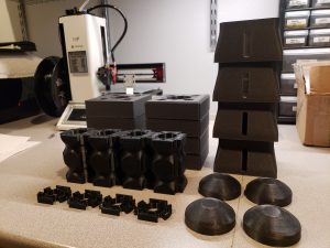
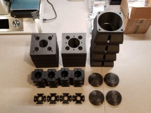
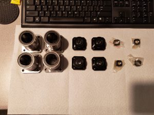
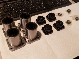
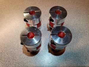
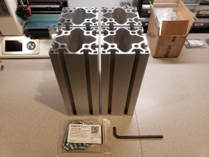
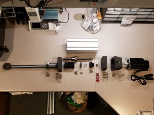
Let’s take a look at all the things we’ll be putting together. It helps to have your workspace neatly organized and all pieces grouped into logical chunks.
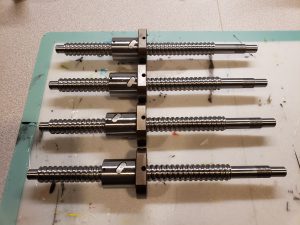
Ball screws:
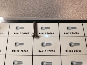
Bolts and nuts:
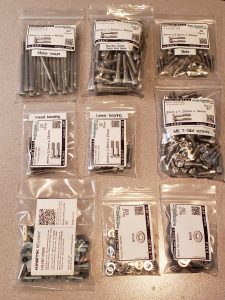
I once again put the label maker to use, and annotated each bolt type with its purpose, for quick reference.
There are additional pieces, which I’ll call out during the build (e.g. o-rings, grease fittings, and more).
As always, you can find links for all of the hardware in bill of materials.
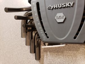
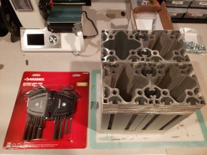
Make sure you also have all the tools, especially a full set of hex keys (metric):
Preparing aluminum profiles – threaded inserts
We’ll begin by screwing on the inserts into profiles. This will either go smoothly, or end up being the toughest part of the whole build – Kinetik has been known for shipping 2 different types of threaded inserts. They both work, but vary tremendously in the difficulty of installation. I was lucky to receive the better variant, but don’t be discouraged if you end up with the other. Bit of patience, persistence, and elbow grease will bring the desired results 😉
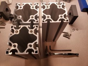
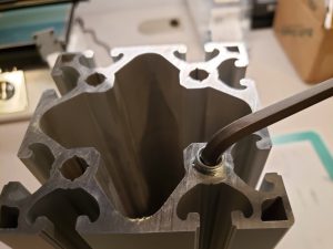
We’ll be using a long hex key. I began by aligning the threaded insert in the hole, putting the long end of the hex key inside the hole to guide it and then making about 1 full rotation. Just enough for the threads to bite into aluminum. Make sure the inserts are going in as straight as possible. This is critical, and can make assembly at a later stage (attaching the bearing mounts and motor mounts) very difficult.
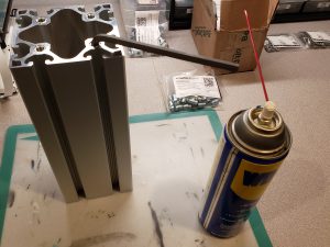
I used a splash of WD-40 on each threaded insert before screwing them on, just to help with the thread cutting:
Once the force required to continue screwing grows, I found that it’s really helpful to put the extrusion on the ground, hold it with one foot, and continue screwing in half-a-turn at a time, then flip extrusion and continue:
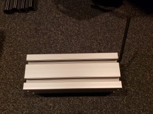
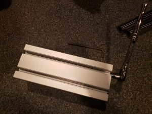
This is a perfect application for a ratchet key with the hex bit – saved me a great deal of time!
It takes about 8 turns total to screw the insert into desired depth. And what’s the desired depth? Inserts should be flush with the end of extrusion, and not protrude above it:
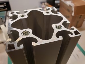
Preparing the profile for first actuator took me about 40 minutes. Having figured out the best approach and helping myself with a ratchet with hex key bit attached, sped it up significantly. I timed myself doing the threaded inserts for very last actuator and I clocked in under 10 minutes for both sides of the profile (8 inserts total). Process improvements can yield great benefits 😉
Greasing the ball screw bearings
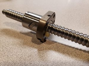
Ball screws are used to transform the rotation of the motor shaft into linear motion of the actuators. They’re carrying the load of the rig. Any unnecessary friction with those elements will contribute to the noise actuators make, and negatively affect performance. This is why it’s important to properly grease them. Note that they may come coated in a thin layer of machine grease, but that’s not a sufficient replacement for proper grease.
Warning: when working with ball screws, make sure not to extend them to a point where the ball nut comes off of the screw. This will result in bearings falling apart and results in a tricky (and time consuming) repair.
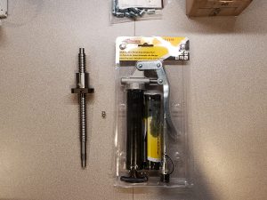
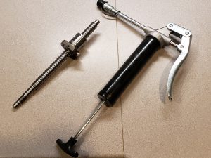
We’ll be using grease gun, and a set of grease fittings (also called “grease nipples”, really 😉 ), that may need to be purchased separately, depending on where did you source the ball screws from. Please see bill of materials for product links.
The process is in fact very simple: load the grease gun with a cartridge, screw the grease fittings to the ball screw nuts, plug the fittings into the nozzle of the grease gun and squeeze the handle 2 times. Then just pull them out of the nozzle – this step takes a bit of force, but it will come off.
Make sure to leave the grease fittings in the ball screw nuts, as they also serve as a seal (even though it doesn’t really matter in the application we’re going to install it), and make it easier to add more grease in future, if we ever have to service the actuators.
You may see some grease oozing from inside of the ball nut – that’s OK, I actually smeared it evenly over the screw itself, and then added some more. Wear nitrile gloves, makes the cleanup easier.
Actuators – Exploded View
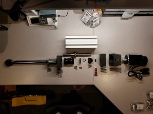
Here’s a quick look into everything that goes into a single actuator:
And trimmed to show just the essentials:
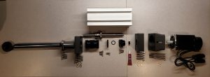
You’ll notice that there’s a large number of differently sized bolts – see the picture above with all the bolts and nuts along with labels, for a quick reference.
Assembling the actuators
The first actuator took me the longest to assemble, I’d estimate around 2-3 hours. I wanted to go through the complete process, as a trial in preparation to then assemble remaining 3 actuators in a single batch, completing the same stage for all of them at once. It’s a convenient approach to make sure we don’t make a mistake for all of them at once and quickly multiply the amount of work. Assembling the remaining 3 actuators resulted in an average time of 1 hour each.
We begin by grabbing the bump stop 3D printed piece and an appropriately sized o-ring:
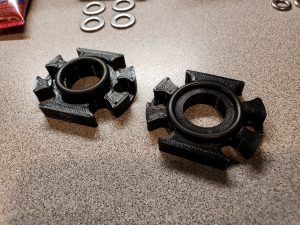
The correct size o-ring is shown on the right side. Notice that it’s expected to fully fit in the groove of the 3D printed part.
If you purchased the same set of o-rings as I called out in bill of materials, here’s a reference to the exact one to use:
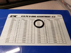
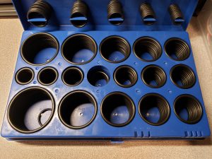
Next, we attach the bump stop on one side of the ball screw nut, and a 3D printed slider on the opposite side:
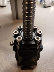
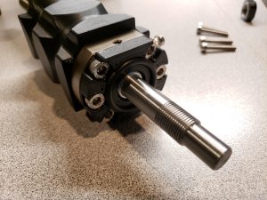
This step may require fair amount of force to drive the bolts into the 3D printer slider. If you have a ratchet with long enough extension (to account for the length of the ball screw without thread), it can speed up the process significantly.
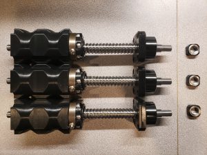
At this point, we need to press the bearing onto the end of ball screw with a small thread. Then secure the bearing with a nut – this is where the small thread is being used:
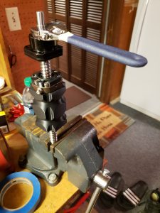
It’s important to really tighten the nut. As you can see, I clamped the ball screw assembly into a vise, and then used adjustable wrench to tighten it. Make sure that the bearing continues to rotate freely – if you encounter signifficant friction, loosen the nut and ensure that bearing has been fully pushed onto the ball screw, as far as it can go.
Finally, tighten the small screw on the nut:
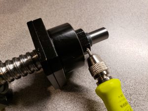
Onto the next step – grab the 3D printed fixed bearing mount, and position the ball screw assembly so that the bearing is inserted into the mount, and the screw holes are aligned:

As you can see, I used a motor mount as a support underneath, to ensure that the protruding part of ball screw doesn’t make it unstable and slide all over the desk as I’m working on attaching the pieces together.
Don’t worry if the o-ring gets in the way here, just move it to the side and screw all the bolts:
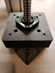
Let’s put everything we’ve assembled so far to the side, and grab one aluminum profile, linear bearing and 3D printed linear bearing mount. Attach the linear bearing mount to one side of the profile (doesn’t matter which one):
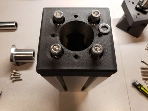
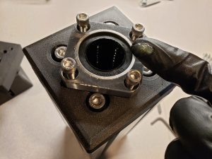
Then insert the linear bearing into the mount, align the holes and start putting the bolts in:
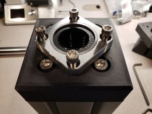
Do not fully tighten the bolts for linear bearing just yet.
Before moving to next step, I additionally spread some grease onto the linear bearing. I’m hoping for smoother and quieter operation, at the cost of a bit of grease oozing onto the hollow shaft in the first few minutes of operation, but that’s easy to clean 😉
Time to put it all together, grab the ball screw assembly, the profile with bearing mounted on one side, and a hollow shaft:
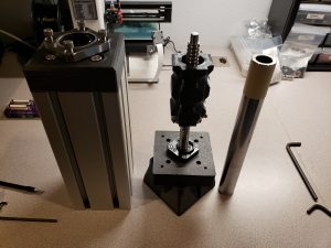
The hollow shafts need to be cleaned. I used a rag (available for cheap from painting supplies section in Home Depot 😉 ) on a wooden dovel and then pushed it back and forth through each shaft. They’re very dirty inside (and smell bad too…) and we don’t want for any debris to get onto the ball screw and affect the operation of the actuator. It doesn’t have to be perfectly clean (although I heard of some people even applying epoxy to coat the inside of shafts), but there should be no more loose debris coming out of you touch the inside walls with your finger.
Once the shafts are ready, try inserting one end into the 3D printed slider, and check the fitment. It should go in with enough resistance to prevent the shaft from falling straight out. If there’s too much wiggle, add a layer of painters tape and then insert it into slider:
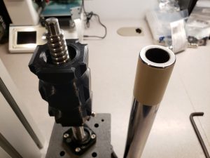
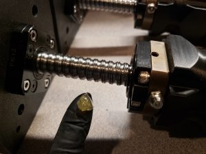
This is last chance to take a look at the insight of the actuator (without having to disassemble it, that its 🙂 ). If you forgot to grease the ball screw nut, now’s the time. I also smeared a bit extra through the length of the screw:
Additionally, you may also want to apply a coat of dry PTFE lube onto the sliders:
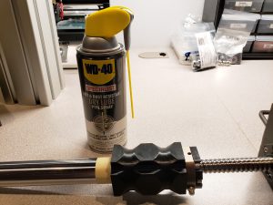
I decided to skip that step – as you may know from my other posts on this blog, I have few parrots 🙂 They have very sensitive respiratory systems, and I wouldn’t take any chances, thus I didn’t want to have any PTFE in the air. It may be reassuring to know, in case you don’t have PTFE spray at hand, that skipping this step didn’t seem to affect the performance of the system.
We can finally put the pieces together – guide the hollow shaft attached to slider and ball screw through the linear bearing installed on the extrusion:
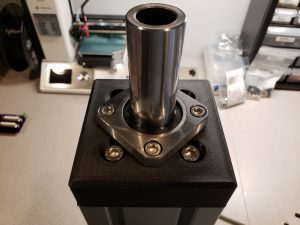
Remember that we didn’t want to tighten the linear bearing bolts before, so that it can be properly seated onto the shaft. We should tighten them now.
Take a look from the other side of the extrusion and put screws through the fixed bearing mount:
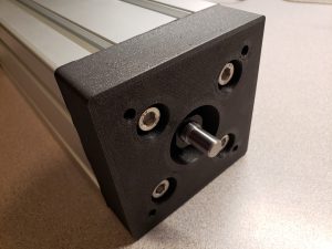
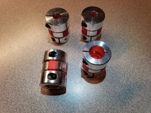
Now let’s grab a coupling, motor mount, motor, and set of appropriate bolts and washers:
We need to remove the “notch” from the motor shaft, as it won’t fit into the couplers we use. It’s easiest to do by grabbing an M3 screw and then driving it onto the notch, until it pushes it away and easily pops out of the shaft:
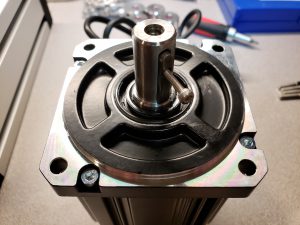
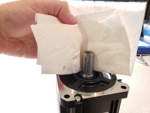
I cleaned the motor shaft, since it came covered in machine grease, with a paper towel dampened with isopropyl alcohol:
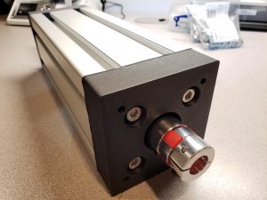
Attach the coupling onto the ball screw shaft, and fully tighten:
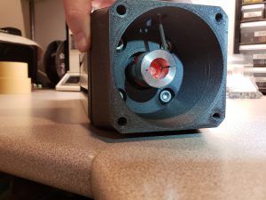
Now, with a motor mount held in place, rotate the coupling so that you can access its nut on the motor shaft side through the opening in the motor mount. This can be a bit counter-intuitive, especially considering the angle of the hex key, so refer to close-up photos:
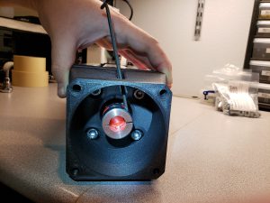
Next, attach the motor and motor mount to the profile, and tighten the coupling onto the motor shaft:
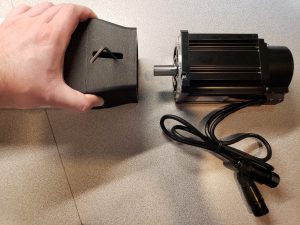
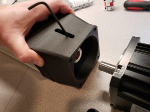
Make sure to first attach the motor to the mount and profile, before fully tightening the coupling. While installing the bolts, the motor mount can slightly compress, which would otherwise lead to the coupling getting squished. This may result in loud noises as the 2 parts of coupling rub against each other. Attaching motor first and then tightening the coupling mitigates this risk.
Original SFX instructions (which can be found here), also recommend to remove the motor at this point (remove the screws, pull 2 halves of the coupling apart) to tighten the screw on the coupling for the motor shaft, but I feel like I was able to tighten it sufficiently through the opening in the mount. And I certainly haven’t noticed any slippage.
Good job! 1 actuator done, 3 more to go 🙂
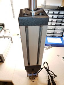
As I mentioned, I approached the assembly in 2 stages:
- first, I assembled single actuator completely, to make sure I learn about the process and resolve any issues before making costly (from time or financial perspective 😉 ) mistakes,
- then I assembled remaining 3 actuators at the same time, to optimize the process (using the same tools I’m already holding, looking up the same bolts and nuts, ensuring consistency across the build, etc.).
Recap of the assembly process
Here’s a quick recap of the complete process as I outlined above, but this time done for 3 actuators simultaneously.
- Screwing the threaded inserts into profiles:
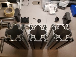
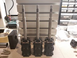
- Attaching the bump stop and slider onto ball screws (remember to grease the ball screw nuts first: grease gun + grease fittings)

- Attaching fixed bearings onto the ball screws (remember to tighten the nuts to keep bearings in place):
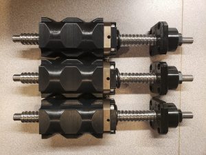
- Screwing fixed bearings onto the 3D printed bearing mounts:
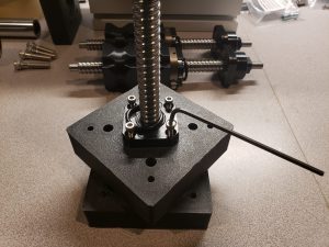
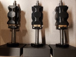
- Attaching linear bearing mounts onto the profiles, and then adding linear bearings:
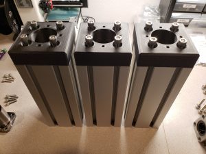
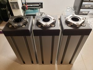
- Inserting hollow shafts into the 3D printed sliders, then putting the ball screw assembly into the profile and finally tightening the linear bearing bolts:
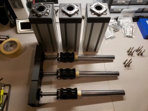
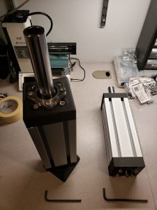
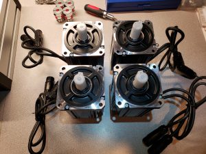
- Using couplings to attach the motors to ball screw shafts, and then bolting down the motors using 3D printed motor mounts:

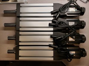
- And done!
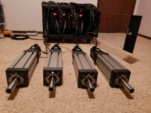
Troubleshooting
- Everything almost works, but 1 actuator behaves incorrectly
- This is usually caused by incorrect wiring. Could be a loose ground connection (double-check that first).
- It may also be caused by slippage on the coupling between motor shaft and ball screw – tighten if needed, by accessing it straight through the window in 3D printed motor mount, by raising the rig first, propping with something and then slowly descending to get the screw positioned so that it can be accessed through the opening.
- To debug further, try swapping the pairs of data cables between Arduino and controllers (DB25 cables) – if the problem moves with the swap, it’s the cable, or wiring/soldering of the Arduino/breakout board. If it remains on the same actuator, it’s either the motor or controller.
- One actuator moves in opposite direction to others
- Check connections for the data cable (encoder data) on the controller. Swapping u, v, w connections will result in opposite/unexpected motion.
- Actuators don’t move when game is running
- Is the stop button engaged? Is it wired correctly (should be connected to NC [normally closed] side.
- Is the connection to Arduino correct?
- Is the right COM port set in SimFeedback?
- Is the wiring from Arduino to controllers correct?
- Can you move motors manually using buttons on controllers in Jog mode? (if not, that moves the suspicion from Arduino and emergency button to motors and controllers.
- Steering wheel, mouse, keyboard or some other peripherals lose connection
- This is caused by EMI – can be remedied by adding shielding to motor cables, or swapping those cables altogether with shielded ones (easier to do if you purchased version B of the motors),
- It may also help to add ferrite rings to all the cables, see bill of materials,
- Jog function doesn’t work
- You’re most likely using the motors on 110V. The first time you start them at this voltage, it will trigger an under-voltage alarm. See how to reset the alarm: Powering the motors on 110V and resetting under-voltage alarm
- Loud squeaky noises when actuators are moving
- Motor coupler may be tightened too closely – 2 halves: motor and linear bearing, may be squeezed too much, resulting in both metal parts of the coupler rubbing against each other. This usually starts being audible after few minutes of the motors running. Note that the 3D printer motor mount may compress slightly during assembly, thus do the final tightening of the coupling through the window in motor mount after attaching the motor to actuator.
On to the final part:
Pingback:DIY Motion Simulator – Part 2 – Electronics, motors, wiring and testing – Bogdan Berg
Pingback:DIY Motion Simulator – Part 4 – Rig, monitor stand, accessories – Bogdan Berg
Pingback:DIY Motion Simulator – Part 1 – Intro, Photos, Shopping List – Bogdan Berg
Hi Bogdan,
I am really impressed with your complete tutorial here for vuilding the sfx 100 project.
I am starting my own build in a few days (parts are dropping in).
The question I have (and i cannot seem to find the answer in any forum) which I hope you can answer. The Arduino bord has a power connecter (6V to 12V). Did you plug in a adapter to power the bord or is it powered by a 3.0 USB connection?
Hope you can help out.
Now I am going to buy you a coffee just for using your guide for the complete build when the parts are in ;-).
Thnx in advance,
Bas
Hi Bas! There’s no need for additional power connection for Arduino. It’s simply powered from the USB port as you mentioned. This is why it’s important to either plug it in directly to your PC’s USB port, or use powered USB hub (with additional power brick for the hub). Using non-powered USB hubs can lead to a situation where Arduino’s power draw won’t be met, and it will read to random restarts and losing the connection.
Hi
im having an issue with one of the servos . When i test them they are perfect button up and down . When i run the Sim feedback all servos on start go in the correct direction but when i hit stop only 3 return and the 4th goes in the other direction .
I tried swaping the cables with another servo same results .
Hey Robert. Hm when stopping the system in Simfeedback, effectively all corners should come down, simply because of gravity. I believe motors are not driving that downwards motion, as it’s not needed, and it’s safer not to do that (e.g. so the limits are not exceeded and unnecessary stress isn’t put on the system).
If upon clicking on stop one of the actuators indeed extends, I wonder if that could have something to do with the signal wiring (the U, V, W connections on the servo controller side). You mentioned swapping cabled with another actuator – did the problem follow the controller, or the actuator?
Maybe the wiring on the motor side is incorrect (did you buy version A or B of the motors?).
Although, if the manual jog test from controller is successful in both directions, this could be pointing to issue with Arduino wiring. Are you using the PCB breakout board by Pyronious, or did you do the Arduino wiring yourself?
Hi Bogdan
I took your concept of using the long end of hex key, down the profile hole, to align the insert a little further and it made the process quite quick.
I took a long “Magnetic Hex Bit Extension” (it just happens to have the same hex size needed for the insert) inserted the long end of the extension through the insert and down the profile hole, the magnetic coupling part stops the extension from falling right through. I then placed a short extension into my cordless drill and then inserted that into the magnetic coupling part, put a little cutting oil in the threaded insert and in a single relatively quick movement drove the insert into the profile hole. The cordless drill I used was a relatively powerful one DEWALT DCD795D2 18V
Once again thanks for your very detailed log an documentary on your build
Superb, what a web site it is! This website provides helpful data to us, keep it up.