Electronics
In this post I’ll try to describe the main components:
- LEDs for indicating the game/board state and showing possible moves,
- Hall effect sensors for detecting if a piece is on the board at a given cell,
- Miscellaneous: power rail, connections to Arduino, etc.
Parts list
- Arduino MEGA – Buy on Amazon
- We’ll be using MEGA, and not i.e. the most popular UNO R3, as we need a lot of I/Os (64 inputs for sensors, outputs for controlling LEDs, any additional inputs i.e. for game reset button, etc.)
- The design could be simplified (i.e. see here), or I/O extenders could be used instead of Arduino MEGA. However, using MEGA also gives us more memory to work with, which comes in handy if we want to implement additional games
- Hall effect sensors (non-latching) – Buy on Amazon
- Quantity: 64 (+few spares just in case)
- Programmable LEDs (WS2812) – Buy on Amazon
- Quantity: 64 (but those are usually purchased in a strip, which is great as we’ll have some spares)
- Note: The strip we purchase has direct repercussions on the design decisions made – the size of game board cells has been selected to match the pitch of LEDs on the strip I purchased. This simplifies the design as we can use the LEDs as they come on the strip (i.e. without the need to re-solder them to achieve any other spacing), and makes the build simpler/faster. For the below strip I used, the pitch is 1.28 inch and the design follows this assumption.
- Magnets
- Requirements: magnets need to fit in the board cell (thus no bigger than the pitch between cells/LEDs), be strong enough to affect the hall sensors, yet at the same time be weak enough to allow magnets be positioned on adjacent cells, without repelling each other
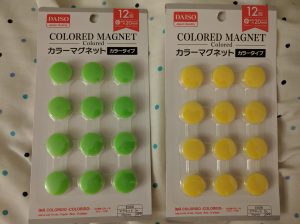
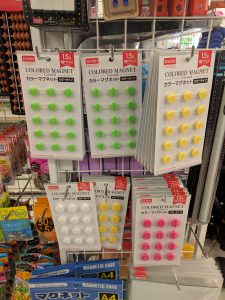
- Link: I found out the best magnets for this project can be found in Daiso (Japanese version of dollar store, everything is $1.50 unless marked otherwise 🙂 ) – they have sets of colorful magnets, 12 in each pack (which just happens to be exactly the number of required pieces per player in checkers!)
- Resistors – Buy on Amazon
- We need a resistor for each hall effect sensor. Those will be soldered onto the custom PCB to make assembly easier. 10k Ohm will work well.
- Power supply – Buy on Amazon
- 5V, at least 5A to have a safe buffer with all LEDs lit up
- DC power jack (male + female) – Buy on Amazon
- DC power jack splitter: 1 female – 3 male – Buy on Amazon
- Hook-up wires – Buy on Amazon (solid core hook-up wires), Buy on Amazon (highly recommend getting few packs of those, very useful)
- 2 line – for power+ ground from main rail to each custom PCB for hall sensors
- 8 line – for signal between Arduino and hall sensors
- Straight headers – Buy on Amazon
- Not required, wires can be soldered directly to the PCBs, but I like the finished look and clean assembly process (when everything pops into place 😉 )
- Perfboards, or prototype PCBs – Buy on Amazon
- I used a universal PCB as a rail for Vcc + ground, for more neat look and easier final assembly (see build photos for more details)
LEDs
As mentioned before, I used a specific strip of programmable LEDs – with a desired pitch between LEDs to simplify the process, so there’s no need to cut and re-solder them, and we can use a complete length per row with connections only between rows.
The length (or to be precise: number of LEDs) is still within acceptable range so that we can feed power from only one end without having to worry about providing it into smaller fragments.
I started with cutting the LED strip into pieces of desired length (8 LEDs for each row), along with wires to connect them all together. Notice the order I used (every other row goes in the opposite direction, to minimize the wiring – this is easy to account for in software):
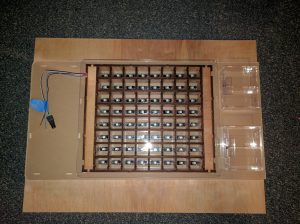
I used the outer most elements of the grid as a guide and glued the LED strip onto the base of the board:
And this is how it all looked in the end, with the grid back in its place:
Hall effect sensors
I went through few iteration between I ended using a custom PCB for mounting the hall effect sensors.
Here’s an overview of my attempts:
- First, I tried soldering the hall effect sensors onto a multi-conductor wire that I was then hoping to guide through the dividers and be able to route all of those wires on a side of the board. This didn’t seem like an optimal solution – too many wires everywhere to keep it organized, hard to position the sensors, etc.
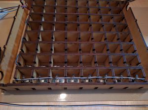
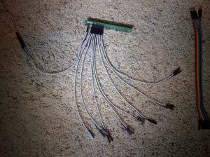
- Before I abandoned that approach, I made this monstrosity:
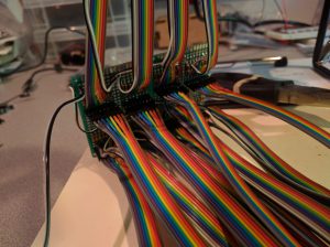
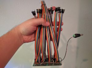
Its purpose was to serve as a bridge between the sensors and Arduino, where each sensor would have it’s resistor… All that soldering done (soldering does bring zen though, doesn’t it? 😉 ), and then I didn’t use it in the end. Oh, and I burned my finger a bit 🙁

- Finally, I came to conclusion that having sensors and resistors on a PCB, one per row, will be the cleanest approach.
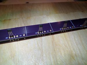
That’s how I chose to proceed – see the details below.
Custom PCB (for sensors and resistors)
I made a design in KiCAD (open source software, fairly easy to learn, and once you get the hang of basics it helps to know the keyboard shortcuts [i.e. for “vias”] which speed up the process significantly).
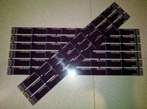
The final PCB dimensions: 11.24 x 0.60 inches (285.60 x 15.34 mm)
You can download the KiCAD project files for this PCB here: smart_chess v5.2 (silk on front and back)
I ordered mine from https://oshpark.com/. I’d recommend them – great service, their panels for manufacturing fill up very quickly, so you won’t have to wait for days before it’s even processed. Without paying for faster processing, the complete turnaround is about 2-3 weeks.
OSHPark requires the orders to be in multiples of 3, so that leaves us with 8 for the board and 1 spare:
Notice that the PCBs are symmetric, so they can be used “from both sides” (front/back) – something I decided to do to keep the overall board layout symmetric – notice which side of the row they’re close to on the top vs bottom half of the board in the last photo below.
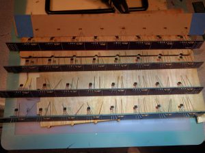
I made a helpful rig to make sure all the sensors are centered and in the same distance from the board (we can see their shadows from the LED highlight, so I wanted to make sure it looks symmetric) and soldered them to the PCB, along with 10kOhm resistors:
Critical thing to keep in mind: make sure the sensors are oriented the right way. That is, all of them are facing the same way, and that this is the right way for them to face – check with the magnets/magnetic game pieces you’ll be using.
The ones I used are unipolar (they react only to one pole from one side, and the other from opposite side) non-latching (as soon as magnet leaves the range, they change state, and don’t require the opposite pole to be in vicinity).
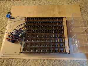
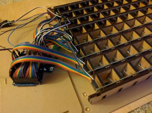
Then each PCB had the headers soldered on and was connected to Arduino Mega (Vcc and Ground were not connected in this step yet):
Miscellaneous (power, Arduino, button)
Powering it all
I used 5V 8A power supply, along with a 1 female – 3 male DC jack splitter (see BOM at the top for details):
- for Arduino
- for LEDs
- and for PCBs with sensors.
Being able to unplug it from Arduino while keeping remaining components powered is handy for when we’re connected to Arduino from laptop through USB – let’s keep things safe 😉
Rail for powering sensors
I used another perfboard to make a quick splitter (Vcc, Gnd) with headers for quick connection to the custom PCBs with sensors:
Connecting it to Arduino
We’re using Arduino Mega because we need a lot of I/O. And since analog ports can be treated as digital (but not the other way, obviously), we have enough of digital I/O to read states of all 64 hall effect sensors, address LEDs, handle switch/button and more (but we’re just 3 outputs short of being able to use LCD screen…).
Note that the software will account for the order in which you connect the rows/sensors, but it’s convenient (and looks better 😉 ) to keep the wires organized.
Button and switch
I must admit that it was a bit of an afterthought. When writing code for the first game (Checkers) I wanted to make sure that the game can be handled using only the pieces on the board (i.e. when current game ends, and the animation indicating winner completes, we go to a state where 2 corners are highlighted, and if all game pieces are removed and only those 2 cells have pieces on them, we restart the game). But that seemed to be limiting (i.e. can’t start a new game without finishing current or having to restart the board altogether) so I added a button.
And switch is there to allow selecting between 2 games, but ultimately I’ll use the reset button to cycle through available games, or add another button, as switch (simplest SPST) limits us to just 2 games.
Testing LEDs
After everything was connected together, it was time to make sure things work as expected 🙂 I wrote simple code to go through the LEDs and light them up. Notice the reversed order in every other row – this is caused by the connection between rows, and will be changed in the software:
Testing sensors
Knowing that LEDs work and I can trust them 🙂 the time has come to verify if all the hall effect sensors react appropriately to the magnetic game pieces. This is also great moment to “calibrate” the sensors – as in, remember which input port in Arduino corresponds to sensor in which cell:
Next, we’ll be bringing life into the electronics:
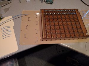
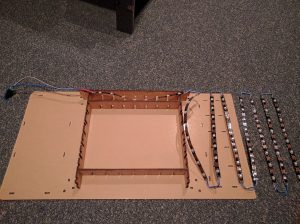

Pingback:Smart Game Board – Mechanical Construction – Bogdan Berg
Pingback:Smart Game Board – Completed! – Bogdan Berg
Great project! I want to do something similar but don’t have any arduino experience. The circuitry you created makes sense and doesn’t include the shift registers I’ve seen. It’s a bit easier for me to wrap my head around. Would love to use your code if you could email it to me. I have an arduino mega and a bunch of hall effect sensor I’ll start soldering 🙂
Hi Richard! Sure thing – I just e-mailed you my code. Please note that it’s very unlikely to just work for you out of the box, because of differences in wiring, but I hope it could be a handy resource 🙂 Good luck with the project!